

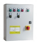
Control panels and systems QT2 BATCH
Product characteristics
DIRECT STARTING WITH THERMAL PROTECTION
FOR WASTEWATERThree phase electromechanical control panel for
two motor pumps.
TECHNICAL DATA
• Power supply 3 ~ 50/60Hz 400V ± 10%;
• Main disconnecting switch with door lock;
• Transformer for power supply of auxiliary circuits;
• Contactor (for each motor);
• Exchanger;
• Protection degree IP 55
INPUTS
• No. 6 extra low voltage inputs for:
– Emergency stop SL / SP STOP (e.g., float switches for protection from dry operation), active in
both AUTOMATIC and MANUAL modes;
– Functional start and stop SL / SP 1 (e.g..: control float switches);
– Maximum level alarm SL / SP MAX;
– Engine block due to temperature sensor tripping
CONTROLS AND SIGNALS
• Selector switch for OFF-AUTOMATIC-MANUAL operation;
– No. 5 indicator lights for the signaling of:
– Presence of power supply;
– Motor pump 1 or 2 running;
– Motor protection tripping 1 or 2
PROTECTION AND ALARMS
• Thermal relay sensitive to the lack of phase internally resettable;
• Motor protection fuses;
• Protection fuses on the auxiliary circuits.
• Alarm output 24Vac active in case of overload protection tripping or maximum level reached.
• Engine block due to temperature sensor tripping.
Selector switch for OFF-AUTOMATIC-MANUAL
operation;
• No. 5 indicator lights for the signaling of:
– Presence of power supply;
– Motor pump 1 or 2 running;
– Motor protection tripping 1 or 2.
PROTECTION AND ALARMS
• Thermal relay sensitive to the lack of phase internally resettable;
• Motor protection fuses;
• Protection fuses on the auxiliary circuits.
• Alarm output 24Vac active in case of overload protection tripping or maximum level reached.
• Engine block due to temperature sensor tripping.